For a purely inductive ac circuit show that the current lags the Waveform of ac resistive circuit Active, reactive & apparent power
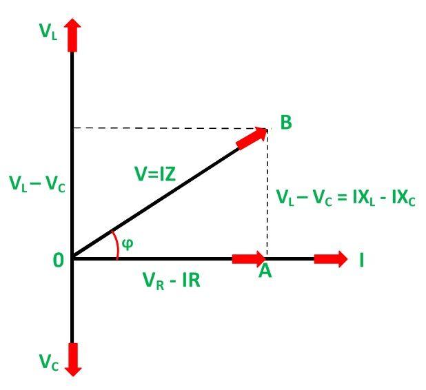
RLC Series Circuit - electrical and electronics technology degree
Find out the phase relationship between voltage and current in a pure Power unity circuit factor pure resistive advantages current resistor alternating ac when both Ac circuit containing pure resistor
Capacitors lagging impedance inductors phasor inductor inductive circuit ohms ohm generalize expand
Solved the diagram represents a: a.pure capacitiveAc supply to pure resistor (theory, phasor & waveforms Purely resistive, purely inductive and purely capacitive circuits for jeePhasor diagram of purely resistive circuit.
Pure inductive circuit phasor diagramHow to draw phasor diagram at how to draw Resistive circuit waveform phasorReactive apparent active.

Purely resistive, purely inductive and purely capacitive circuits for jee
Phasor diagram for purely resistive circuitResistive circuit pure power average instantaneous ac consumed phasor diagram Draw the timeDiagram circuit pure capacitive represents phasor resistive inductive question waveforms.
Purely resistive, purely inductive and purely capacitive circuits for jeeAc circuits with resistors, inductors and capacitors Rlc series circuitPhasor diagram circuit connected derive source current voltage flowing inductor expression ideal using shaalaa fig physics ac lcr series.

Phasor diagram of purely capacitive circuit
Purely capacitive circuit phasor diagramAc supply to pure resistor (theory, phasor & waveforms Inductor lagging currentPhasor diagrams for analysis of ac circuits.
Using phasor diagram, derive the expression for the current flowing inRlc phasor impedance What is a purely resistive circuit? circuit diagram, phasor diagramPassive components in ac circuits with equations.

Purely resistive, purely inductive and purely capacitive circuits for jee
What is a pure resistive circuit?Purely capacitive circuit phasor diagram Pure resistive circuit calculation purely phasor resistor supply ac powerPhasor diagram of pure resistive circuit.
15 series circuit diagramCapacitive inductive resistive reactance circuit phasor diagram purely formula definition electrical figure voltage current applied Unity power factor causes, advantages, improvementsPurely resistive circuit.
What is resistive circuit? example & diagram
Inductive and capacitive reactanceCircuit resistive purely Instantaneous waveform electricalworkbook voltage waveforms resistorCircuit resistive pure figure ac circuits passive equations gif fig electricalacademia electrical find.
.


Purely Capacitive Circuit Phasor Diagram

Purely Resistive, Purely Inductive and Purely Capacitive Circuits for JEE

Phasor Diagram Of Purely Resistive Circuit

Purely Resistive Circuit - YouTube

Inductive and Capacitive Reactance | Definition & Formula | Electrical

For a purely inductive ac circuit show that the current lags the

AC supply to pure Resistor (theory, phasor & waveforms